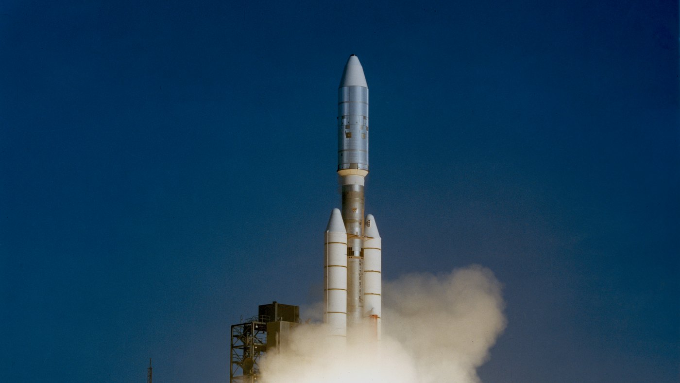
On October 11, 2018, a side booster of the Soyuz MS-10 rocket struck the main stage two minutes after liftoff, forcing the capsule to separate and perform a steep, uncontrolled plunge back into the atmosphere. Cosmonaut Aleksey Ovchinin reported a peak load of 6.7 g during the descent.1 His NASA colleague Nick Hague noted shortly after that experienced astronauts typically endure four to five g's during standard re-entry, making the emergency descent an intense but survivable event.
By contrast, the Space Shuttle experienced only about 1.5 g during its return from orbit, a target value set by NASA engineers during the program's initial mission planning.2 Sierra Space’s wing-bodied cargo vehicle, Dream Chaser, anticipates its first flight with a similar operational goal: a re-entry force under 1.5 g followed by a standard runway landing.3 While wings and lift-generating bodies certainly soften the landing, the physics of thermal management proves far more complicated.
- How the lift-to-drag ratio determines the difference in structural load between capsules and spaceplanes.
- Why wings reduce peak thermal stress while increasing the total heat soak of the vehicle.
- The physical factors behind extreme heat localization in winged spacecraft.
- The challenges of skipping re-entry for capsule heat shields and forthcoming 2026 technical mitigations.
How does lift-to-drag ratio reduce re-entry forces?
Every spacecraft entering the atmosphere must dissipate its orbital kinetic energy through aerodynamic friction. Engineers measure the efficiency of this process using the lift-to-drag ratio, or L/D. The Apollo command module featured an offset center of gravity, allowing it to enter the atmosphere at an angle and generate lift equal to roughly one-third of its drag. Data from Apollo 11 confirms an L/D ratio of approximately 0.30.4 The Space Shuttle, by flying with its nose pitched 40 degrees upward, pushed this ratio toward 1.0.25
The impact of this ratio on structural load is mathematically clear. When a vehicle slows down through gliding, lift supports a significant portion of its weight. The resulting load felt by the crew is the vector sum of drag and gravity. At a ratio of 0.30, the peak load is approximately 3.5 g, whereas at a ratio of 1.0, the load drops to 1.4 g. Because real-world capsule trajectories are often steeper than ideal models, they remain well above these theoretical floors. NASA's report on Soyuz operations cites typical re-entry loads of 4-5 g, with ballistic (non-lifting) re-entries reaching 8-10 g.6
The second major advantage of lift is its influence on entry angles. In 1960, NASA researcher Thomas Wong calculated that a vehicle restricted to 10 g could safely navigate an atmospheric entry corridor three to five times wider if lift were utilized.7 The Space Shuttle could bank to redirect this lift, allowing for a cross-range capability of approximately 750 nautical miles (1,390 kilometers), significantly increasing the number of available landing sites.
Why does higher lift reduce peak temperature but increase total heat soak?
Lift allows a vehicle to remain in the thinner, upper atmosphere for a longer duration, delaying its descent into denser air. A 2024 master's thesis by Sibel Kaçmaz at Middle East Technical University, supervised by Prof. Dr. Serkan Özgen, calculated that a shuttle-like vehicle reaches peak heating at an altitude of 71 kilometers and experiences maximum deceleration at 45 kilometers.5 Conversely, a ballistic trajectory reaches its thermal peak between 30 and 46 kilometers. The thinner the air, the lower the peak heat flux hitting the surface.
However, this is balanced by the duration of exposure. The Space Shuttle spent roughly 30 minutes dissipating its orbital energy. NASA engineer B. Kent Joosten noted that this prolonged, high-altitude glide caused heat to soak deeper into the internal structure, meaning the temperature of the aluminum airframe behind the heat shield often dictated the mission profile more strictly than exterior surface temperatures. This necessitated thermal planning even while in orbit, where the vehicle’s underbelly was oriented away from the sun to minimize pre-entry heat buildup.2 Wong's 1960 analysis similarly found that for vehicles with a constant L/D ratio, the thermal penalty becomes significantly more severe once the ratio exceeds 1.0.7
Notes and Sources
- Spaceflight Now (2018). "Soyuz crew lands safely after emergency launch abort."
- Joosten, B. K. (1985). "Descent Guidance and Mission Planning for Space Shuttle." NASA Technical Reports Server 19850008593.
- Sierra Space (2026). "Sierra Space Secures National Security and Commercial Payload Contracts for Dream Chaser Inaugural Flight."
- Graves, C. A., Harpold, J. C. (1972). "Apollo Experience Report: Mission Planning for Apollo Entry." NASA TN D-6725.
- Kaçmaz, S. (2024). "Trajectory Optimization of a Lifting Re-entry Vehicle." Master's Thesis, Middle East Technical University.
- NASA (2010). "NASA Astronauts on Soyuz: Experience and Lessons for the Future." NASA/SP-2010-578.
- Wong, T. J. (1960). "Motion and Heating During Atmosphere Reentry of Space Vehicles." NASA TN D-334.
- Allen, H. J., Eggers, A. J. (1958). "A Study of the Motion and Aerodynamic Heating of Ballistic Missiles." NACA Report 1381.
- Columbia Accident Investigation Board (2003). Report, Volume I.
- NASA (2024). "NASA Identifies Cause of Artemis I Orion Heat Shield Char Loss."
- NASA (2026). "Rigorous Analysis Confirms NASA's Artemis II Heat Shield Performance."